

41. Why Should You Run A Background With A Single Beam Ft-ir Instrument?
How an FTIR Spectrometer Operates
- Page ID
- 1844
FTIR spectrometers (Fourier Transform Infrared Spectrometer) are widely used in organic synthesis, polymer scientific discipline, petrochemical engineering science, pharmaceutical industry and nutrient analysis. In add-on, since FTIR spectrometers tin exist hyphenated to chromatography, the mechanism of chemical reactions and the detection of unstable substances tin can be investigated with such instruments.
Introduction
The range of Infrared region is 12800 ~ 10 cm-1 and can exist divided into most-infrared region (12800 ~ 4000 cm-1), mid-infrared region (4000 ~ 200 cm-1) and far-infrared region (50 ~ 1000 cm-1). The discovery of infrared light can be dated back to the 19th century. Since then, scientists have established various ways to utilise infrared lite. Infrared assimilation spectroscopy is the method which scientists use to determine the structures of molecules with the molecules' characteristic assimilation of infrared radiation. Infrared spectrum is molecular vibrational spectrum. When exposed to infrared radiation, sample molecules selectively absorb radiation of specific wavelengths which causes the change of dipole moment of sample molecules. Consequently, the vibrational energy levels of sample molecules transfer from ground state to excited land. The frequency of the assimilation peak is determined by the vibrational energy gap. The number of absorption peaks is related to the number of vibrational freedom of the molecule. The intensity of absorption peaks is related to the change of dipole moment and the possibility of the transition of free energy levels. Therefore, by analyzing the infrared spectrum, one can readily obtain abundant construction information of a molecule. Most molecules are infrared active except for several homonuclear diatomic molecules such as Oii, Due north2 and Clii due to the zero dipole change in the vibration and rotation of these molecules. What makes infrared absorption spectroscopy fifty-fifty more than useful is the fact that it is capable to analyze all gas, liquid and solid samples. The common used region for infrared assimilation spectroscopy is 4000 ~ 400 cm-1 because the absorption radiation of most organic compounds and inorganic ions is within this region.
FTIR spectrometers are the third generation infrared spectrometer. FTIR spectrometers accept several prominent advantages: (1) The signal-to-noise ratio of spectrum is significantly higher than the previous generation infrared spectrometers. (2) The accuracy of wavenumber is high. The error is within the range of ± 0.01 cm-ane. (3) The scan time of all frequencies is short (approximately 1 s). (iv) The resolution is extremely high (0.ane ~ 0.005 cm-1). (5) The scan range is wide (1000 ~ 10 cm-1). (vi) The interference from stray calorie-free is reduced. Due to these advantages, FTIR Spectrometers have replaced dispersive IR spectrometers.
Evolution of IR Spectrometers
Up till FTIR spectrometers, there have been three generations of IR spectrometers.
- The first generation IR spectrometer was invented in belatedly 1950s. Information technology utilizes prism optical splitting system. The prisms are made of NaCl. The requirement of the sample's water content and particle size is extremely strict. Farther more, the scan range is narrow. Additionally, the repeatability is fairly poor. Equally a result, the first generation IR spectrometer is no longer in employ.
- The second generation IR spectrometer was introduced to the world in 1960s. It utilizes gratings as the monochrometer. The performance of the second generation IR spectrometer is much improve compared with IR spectrometers with prism monochrometer, Merely there are notwithstanding several prominent weaknesses such as low sensitivity, low scan speed and poor wavelength accuracy which rendered information technology out of date later the invention of the third generation IR spectrometer.
- The invention of the 3rd generation IR spectrometer, Fourier transform infrared spectrometer, marked the abdication of monochrometer and the prosperity of interferometer. With this replacement, IR spectrometers became exceptionally powerful. Consequently, diverse applications of IR spectrometer accept been realized.
Dispersive IR Spectrometers
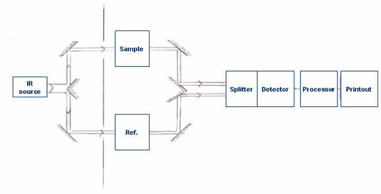
To understand the powerfulness and usefulness of FTIR spectrometer, information technology is essential to have some background information of dispersive IR Spectrometer. The basic components of a dispersive IR spectrometer include a radiations source, monochromator, and detector. The mutual IR radiation sources are inert solids that are heated electrically to promote thermal emission of radiation in the infrared region of the electromagnetic spectrum. The monochromator is a device used to disperse or split up a wide spectrum of IR radiation into private narrow IR frequencies.
Generally, dispersive spectrometers have a double-beam design with two equivalent beams from the same source passing through the sample and reference chambers as independent beams. These reference and sample beams are alternately focused on the detector past making utilise of an optical chopper, such equally, a sector mirror. One beam volition proceed, traveling through the sample, while the other beam will pass through a reference species for analytical comparison of transmitted photon wavefront information.
Later the incident radiations travels through the sample species, the emitted wavefront of radiation is dispersed by a monochromator (gratings and slits) into its component frequencies. A combination of prisms or gratings with variable-slit mechanisms, mirrors, and filters comprise the dispersive system. Narrower slits gives meliorate resolution by distinguishing more closely spaced frequencies of radiation and wider slits allow more than light to reach the detector and provide improve system sensitivity. The emitted wavefront beam (analog spectral output) hits the detector and generates an electrical signal equally a response.
Detectors are devices that convert the analog spectral output into an electrical signal. These electric signals are further processed by the computer using mathematical algorithm to get in at the final spectrum. The detectors used in IR spectrometers can be classified as either photon/breakthrough detectors or thermal detectors.
It is the assimilation of IR radiation by the sample, producing a modify of IR radiation intensity, which gets detected as an off-null signal (due east.m. unlike from reference indicate). This modify is translated into the recorder response through the deportment of synchronous motors. Each frequency that passes through the sample is measured individually by the detector which consequently slows the process of scanning the entire IR region. A cake diagram of a archetype dispersive IR spectrometer is shown in Figure \(\PageIndex{ane}\).
FTIR Spectrometers
The Components of FTIR Spectrometers
A mutual FTIR spectrometer consists of a source, interferometer, sample compartment, detector, amplifier, A/D convertor, and a computer. The source generates radiation which passes the sample through the interferometer and reaches the detector. And then the signal is amplified and converted to digital indicate by the amplifier and analog-to-digital converter, respectively. Somewhen, the signal is transferred to a computer in which Fourier transform is carried out. Figure \(\PageIndex{ii}\) is a block diagram of an FTIR spectrometer.
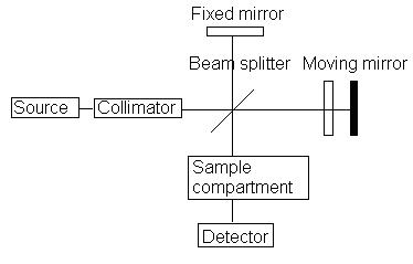
The major deviation between an FTIR spectrometer and a dispersive IR spectrometer is the Michelson interferometer.
Michelson Interferometer
The Michelson interferometer, which is the core of FTIR spectrometers, is used to carve up one beam of light into two so that the paths of the two beams are different. Then the Michelson interferometer recombines the two beams and conducts them into the detector where the divergence of the intensity of these 2 beams are measured as a function of the difference of the paths. Figure \(\PageIndex{3}\) is a schematic of the Michelson Interferometer.
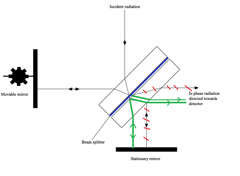
A typical Michelson interferometer consists of two perpendicular mirrors and a beamsplitter. I of the mirror is a stationary mirror and some other i is a movable mirror. The beamsplitter is designed to transmit half of the light and reflect half of the light. Subsequently, the transmitted light and the reflected light strike the stationary mirror and the movable mirror, respectively. When reflected back by the mirrors, two beams of light recombine with each other at the beamsplitter.
If the distances travelled by ii beams are the same which means the distances between ii mirrors and the beamsplitter are the aforementioned, the situation is defined as nix path difference (ZPD). Simply imagine if the movable mirror moves abroad from the beamsplitter, the light axle which strikes the movable mirror will travel a longer distance than the light beam which strikes the stationary mirror. The distance which the movable mirror is away from the ZPD is defined as the mirror deportation and is represented past ∆. It is obvious that the extra altitude travelled by the low-cal which strikes the movable mirror is 2∆. The extra distance is defined as the optical path difference (OPD) and is represented by delta. Therefore,
\[\delta =2\Delta \label{1}\]
It is well established that when OPD is the multiples of the wavelength, effective interference occurs because crests overlap with crests, troughs with troughs. As a effect, a maximum intensity signal is observed by the detector. This situation can be described by the following equation:
\[\delta =northward\lambda \label{2}\]
with n = 0,i,two,iii...
In dissimilarity, when OPD is the half wavelength or half wavelength add together multiples of wavelength, destructive interference occurs because crests overlap with troughs. Consequently, a minimum intensity signal is observed past the detector. This situation can exist described by the post-obit equation:
\[\delta =(n+\dfrac{1}{ii})\lambda \label{3} \]
with n = 0,1,2,3...
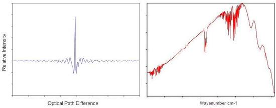
These two situations are 2 farthermost situations. If the OPD is neither north-fold wavelengths nor (n+ane/ii)-fold wavelengths, the interference should be between constructive and subversive. And then the intensity of the signal should be between maximum and minimum. Since the mirror moves dorsum and forth, the intensity of the signal increases and decreases which gives rise to a cosine wave. The plot is divers as an interferogram. When detecting the radiation of a broad band source rather than a single-wavelength source, a peak at ZPD is found in the interferogram. At the other distance scanned, the signal decays quickly since the mirror moves back and along. Figure \(\PageIndex{4}\)(a) shows an interferogram of a wide band source.
Fourier Transform of Interferogram to Spectrum
The interferogram is a function of time and the values outputted by this function of time are said to make upwardly the time domain. The time domain is Fourier transformed to get a frequency domain, which is deconvolved to product a spectrum. Effigy \(\PageIndex{4}\) shows the Fast Fourier transform from an interferogram of polychromatic light to its spectrum.
The Fourier Transform
The outset one who found that a spectrum and its interferogram are related via a Fourier transform was Lord Rayleigh. He fabricated the detect in 1892. Merely the first one who successfully converted an interferogram to its spectrum was Fellgett who fabricated the achievement after more than half a century. Fast Fourier transform method on which the modern FTIR spectrometer based was introduced to the world by Cooley and Turkey in 1965 . Information technology has been applied widely to analytical methods such as infrared spectrometry, nuclear magnetic resonance and mass spectrometry due to several prominent advantages which are listed in Table \(\PageIndex{ane}\) .
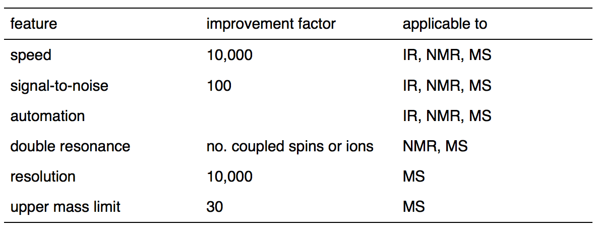
Table \(\PageIndex{1}\). Advantages of Fourier Transform over Continuous-Wave Spectrometry
Fourier transform, named after the French mathematician and physicist Jean Baptiste Joseph Fourier, is a mathematical method to transform a function into a new function. The following equation is a mutual form of the Fourier transform with unitary normalization constants:
\[F(\omega )=\dfrac{1}{\sqrt{2\pi }}\int_{-\infty}^{\infty}f(t)due east^{-i\omega t}dt \characterization{4}\]
in which t is time, i is the square root of -1.
The following equation is some other form of the Fourier transform(cosine transform) which applies to real, even functions:
\[F(\nu )=\dfrac{ane}{\sqrt{2\pi }}\int_{-\infty}^{\infty}f(t)\cos(2\pi \nu t)dt \label{five}\]
The following equation shows how f(t) is related to F(v) via a Fourier transform:
\[f\left ( t \right )=\dfrac{one}{\sqrt{ii\pi }}\int_{-\infty}^{\infty}F(\nu )\cos(two\pi \nu t)d\nu \label{6}\]
An Alternative Explanation of the Fourier Transform in FTIR Spectrometers
The math description of the Fourier transform can be tedious and confusing. An alternative explanation of the Fourier transform in FTIR spectrometers is provided hither before we leap into the math clarification to give you a rough impression which may help yous sympathise the math description.
The interferogram obtained is a plot of the intensity of point versus OPD. A Fourier transform can exist viewed as the inversion of the independent variable of a function. Thus, Fourier transform of the interferogram can be viewed as the inversion of OPD. The unit of measurement of OPD is centimeter, so the inversion of OPD has a unit of measurement of inverse centimeters, cm -1 . Inverse centimeters are as well known as wavenumbers. After the Fourier transform, a plot of intensity of signal versus wavenumber is produced. Such a plot is an IR spectrum. Although this caption is piece of cake to understand, it is non perfectly rigorous.
Simplified Math Description of the Fourier Transform in FTIR
The wave functions of the reflected and transmitted beams may be represented by the general form of:
\[E_{1}=rtc E_{1000}\times \cos(\nu t-2\pi kx) \label{7}\]
and
\[E_{1}=rtc E_{chiliad}\times \cos[\nu t-ii\pi yard(\nu x+\Delta d)] \label{eight}\]
where
- \(\Delta{d}\) is the path divergence,
- \(r\) is the reflectance (amplitude) of the beam splitter,
- \(t\) is the transmittance, and
- \(c\) is the polarization constant.
The resultant moving ridge function of their superposition at the detector is represented every bit:
\[E=E_{i}+E_{ii}=2(r\times t\times c\times E_{m})\times \cos(\nu t-2\pi kx)\cos(\pi k\Delta d) \label{9}\]
where Eyard,, ν, and g are the amplitude, frequency and wave number of the IR radiation source.
The intensity (\(I\)) detected is the time average of \(E_2\) and is written as
\[I=4r^{2}t^{2}c^{ii}E_{thousand}^{2}cos^{two}(\nu t-2\pi kx)\cos^{2}(\pi k\Delta d) \characterization{x}\]
Since the time boilerplate of the first cosine term is but ½, then
\[I=2I(k)\cos^{ii}(\pi k\Delta d) \label{11}\]
and
\[I(\Delta d)=I(k)[one+\cos(2\pi k\Delta d)]\characterization{12}\]
where \(I(yard)\) is a constant that depends only upon \(k\) and \(I(∆d)\) is the interferogram .
From \(I(∆d)\) we tin get \(I(g)\) using Fourier transform every bit follows:
\[I(\Delta d)-I(\infty)=\int_{0}^{k_{m}}I(yard)\cos(ii\Pi g\Delta d)dk \label{13}\]
Letting Kthousand →∞, we can write
\[I(k)=\int_{0}^{\infty}[I(\Delta d)-I(\infty)]\cos(ii\Pi k\Delta d)d\Delta d \label{14}\]
The physically measured information recorded at the detector produces an interferogram, which provides data near a response change over time within the mirror scan altitude. Therefore, the interferogram obtained at the detector is a fourth dimension domain spectrum. This process involves sampling each position, which tin take a long time if the signal is pocket-sized and the number of frequencies being sampled is large.
In terms of ordinary frequency, \(\nu\), the Fourier transform of this is given past (angular frequency \(\omega= s\pi \nu\)):
\[f(\nu )=\int_{-\infty}^{\infty}f(t)due east^{-i2\Pi \nu t}dt \label{15}\]
The changed Fourier transform is given by:
\[f(\nu )=\int_{-\infty}^{\infty}f(t)due east^{+i2\pi \nu t}dt \label{16}\]
The interferogram is transformed into IR absorption spectrum (Figure \(\PageIndex{5}\)) that is commonly recognizable with absorption intensity or % transmittance plotted against the wavelength or wavenumber. The ratio of radiant ability transmitted by the sample (I) relative to the radiant power of incident light on the sample (I0) results in quantity of Transmittance, (T). Absorbance (A) is the logarithm to the base ten of the reciprocal of the transmittance (T):
\[A=log_{10}\dfrac{1}{T}=-log_{x}T=-log_{10}\dfrac{I}{I_{0}} \label{17}\]
Hands-on Operation of an FTIR Spectrometer
Pace 1 : The first step is sample preparation. The standard method to prepare solid sample for FTIR spectrometer is to use KBr. Nigh 2 mg of sample and 200 mg KBr are stale and ground. The particle size should be unified and less than two micrometers. And so, the mixture is squeezed to form transparent pellets which can be measured straight. For liquids with high boiling point or viscous solution, it can exist added in between two NaCl pellets. So the sample is fixed in the jail cell by skews and measured. For volatile liquid sample, it is dissolved in CS2 or CCl4 to form 10% solution. Then the solution is injected into a liquid cell for measurement. Gas sample needs to be measured in a gas cell with two KBr windows on each side. The gas prison cell should beginning be vacuumed. Then the sample can be introduced to the gas cell for measurement.
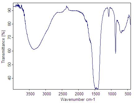
Stride 2: The second step is getting a background spectrum by collecting an interferogram and its subsequent conversion to frequency data by inverse Fourier transform. We obtain the groundwork spectrum because the solvent in which we identify our sample will have traces of dissolved gases besides as solvent molecules that contribute information that are not our sample. The background spectrum will contain information nearly the species of gases and solvent molecules, which may then exist subtracted abroad from our sample spectrum in social club to proceeds data about just the sample. Figure \(\PageIndex{6}\) shows an example of an FTIR background spectrum.
The groundwork spectrum also takes into account several other factors related to the musical instrument performance, which includes information most the source, interferometer, detector, and the contribution of ambient water (note the 2 irregular groups of lines at about 3600 cm–1 and about 1600 cm–1 in Figure \(\PageIndex{half dozen}\)) and carbon dioxide (note the doublet at 2360 cm–1 and precipitous spike at 667 cm–ane in Effigy \(\PageIndex{six}\)) present in the optical bench.
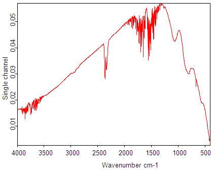
Step 3: Next, we collect a single-beam spectrum of the sample, which will incorporate absorption bands from the sample also every bit the groundwork (gaseous or solvent).
Stride 4: The ratio between the single-beam sample spectrum and the single beam background spectrum gives the spectrum of the sample (Figure \(\PageIndex{7}\)).

Stride 5: Data analysis is done past assigning the observed assimilation frequency bands in the sample spectrum to appropriate normal modes of vibrations in the molecules.
Portable FTIR Spectrometers
Despite of the powerfulness of traditional FTIR spectrometers, they are not suitable for real-time monitoring or field use. So various portable FTIR spectrometers have been adult. Beneath are ii examples.
Ahonen et al developed a portable, existent-time FTIR spectrometer as a gas analyzer for industrial hygiene use. The instrument consists of an operational keyboard, a control console, indicate and control processing electronics, an interferometer, a heatable sample prison cell and a detector. All the components were packed into a cart. To minimize the size of the instrument, the resolution of FTIR spectrometer was sacraficed. But it is good enough for the use of industrial hygiene. The correlation coefficient of aseptic upshot betwixt the analyzer and adsorption tubes is about 1 mg/miii.
Korb et al developed a portable FTIR spectrometer which only weighs about 12.5 kg and so that it can exist held by hand. Moreover, the free energy source of the instrument is bombardment so that the mobility is significantly enhanced. Likewise, the instrument can office well within the temperature range of 0 to 45 oC and the humidity range of 0 to 100%. Additionally, this instrument resists vibration. Information technology works well in an operating helicopter. Consequently, this musical instrument is excellent for the analysis of radiation from the surface and temper of the Earth. The instrument is as well very stable. After a three-year operation, information technology did not lose optical alignment. The reduction of size was implemented by a artistic pattern of optical arrangement and accessory components. Two KBr prisms were used to institute the interferometer cavity. Optical coatings replaced the mirrors and beam splitter in the interferometer. The optical path is shortened with a much more meaty packaging of components. A pocket-size, low energy consuming interferometer drive was designed. It is besides mass balanced to resist vibration. The mutual He-Ne tube was replaced past a smaller light amplification by stimulated emission of radiation diode.
References
- Scientific discipline, 2i, 1983, 297
- W.D. Perkins, "Fourier Transform-Infrared Spectroscopy". Office ane. Instrumentation. Topics in Chemic Instrumentation. Ed. Frank A. Settle, Jr. Journal of Chemical Education, 63:1, January 1986: A5-A10.
- D.A. Skoog and J.J. Leary. "Principles of Instrumental Analysis, 4thursday Ed.", Harcourt Brace Jovanovich. Philadelphia, PA, 1992. Chapter 12.
- F. Daniels, J.W. Williams, P. Bender, R.A. Alberty, C.D. Cornwell, J. Due east. Harriman. "Experimental Physical Chemistry, 7th Ed.", McGraw-Hill, New York, NY, 1970.
- J.West. Cooley and J.W. Turkey, Math. Comp., 1965, xix, 9
- A.G. Marshall, Acc. Chem. Res., 1985, eighteen, 316
- A. R. Korb, P. Dybwad, W. Wadsworth, J. W. Salisbury, Applied Eyes, 1996, 35, 1679
- I. Ahonen, H. Riipinen, A. Roos, Analyst, 1996, 121, 1253
- D. Due west. Brawl, Field Guide to Spectroscopy, SPIE Publication, Bellingham, 2006
- Five. Saptari, Fourier-Transform Spectroscopy Instrumentation Engineering, SPIE Publication, Bellingham, 2003
- P. R. Griffiths, J. A. de Haseth, Fourier Transform Infrared Spectrometry, Wiley, New York, 1986
- B. C. Smith, Fundamentals of Fourier Transform Infrared Spectroscopy, CRC press, 1996
- B. Stuart, Modern Infrared Spectroscopy, Wiley, New York, 1996
- A. Fifty. Smith, Practical Infrared Spectroscopy : Fundamentals, Techniques, and Analytical Trouble-solving, Wiley, New York, 1979
- P. R. Griffiths, Chemical Infrared Fourier Transform Spectroscopy, Wiley, New York, 1975
Contributors and Attributions
- Nancy Birkner (UCD), Qian Wang (UCD)

41. Why Should You Run A Background With A Single Beam Ft-ir Instrument?,
Source: https://chem.libretexts.org/Bookshelves/Physical_and_Theoretical_Chemistry_Textbook_Maps/Supplemental_Modules_%28Physical_and_Theoretical_Chemistry%29/Spectroscopy/Vibrational_Spectroscopy/Infrared_Spectroscopy/How_an_FTIR_Spectrometer_Operates
Posted by: hoskinnoten1939.blogspot.com
0 Response to "41. Why Should You Run A Background With A Single Beam Ft-ir Instrument?"
Post a Comment